What Is a 3D Printer for Metal?
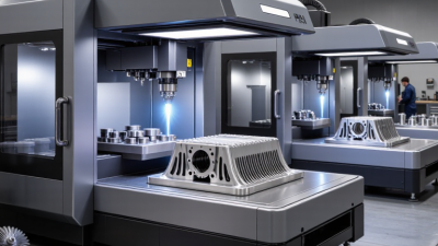
A 3d printer for metal builds parts layer by layer from a digital model, using metal powder or wire as feedstock. In powder-bed fusion, a laser or electron beam selectively melts fine metal powder; the build chamber, recoater, and support structures all affect the result. The finished part may still need heat treatment, support removal, or machining. It is not a one-step shortcut.
The market is growing, but the numbers need context. Wohlers Report 2024, published by ASTM International, estimated the global additive-manufacturing industry at $20.035 billion in 2023, up 11.1% from 2022. That figure covers additive manufacturing broadly, not metal printers alone. Terry Wohlers, a longtime industry analyst, has emphasized in his published analysis that production readiness depends on reliable processes, not headlines or machine sales. This is a paraphrase, not a verbatim quotation. A printer can make a striking sample; repeatable quality across a production run is harder. Small details matter, from powder handling to how a part cools.
There are trade-offs. Metal systems can produce complex geometries and consolidate assemblies, yet machines, materials, and post-processing carry real costs. A thin lattice may look elegant on screen and prove difficult to clean or inspect. That is worth remembering. This guide explains what a metal 3D printer does, how common processes differ, and where the technology makes practical sense.
What Defines a Metal 3D Printer Under ISO/ASTM 52900?
Under ISO/ASTM 52900, additive manufacturing means making parts from 3D model data by joining material, usually layer by layer. The standard describes process categories; it does not create one separate technical category called “metal 3D printer.” That distinction matters.
A metal 3D printer is therefore a machine configured to build parts from metal feedstock using an additive process. Powder bed fusion selectively melts or binds powder in a controlled chamber. Directed energy deposition feeds metal powder or wire into a focused energy source, creating a bead that fuses to the part. Binder jetting joins powder with a liquid binder; the printed part usually needs later processing, such as sintering. Different methods produce different surface textures, internal features, and material properties.
Look beyond the label. Check the feedstock form, energy source, atmosphere, build area, and required post-processing. A rough, granular surface may be normal for one process, while another may leave visible deposition lines. In practice, “metal printer” can be an imprecise shorthand. The machine, material, settings, and finishing steps together determine what part it can reliably produce.
How Powder Bed Fusion Forms Parts in Layers About 20–100 μm Thick
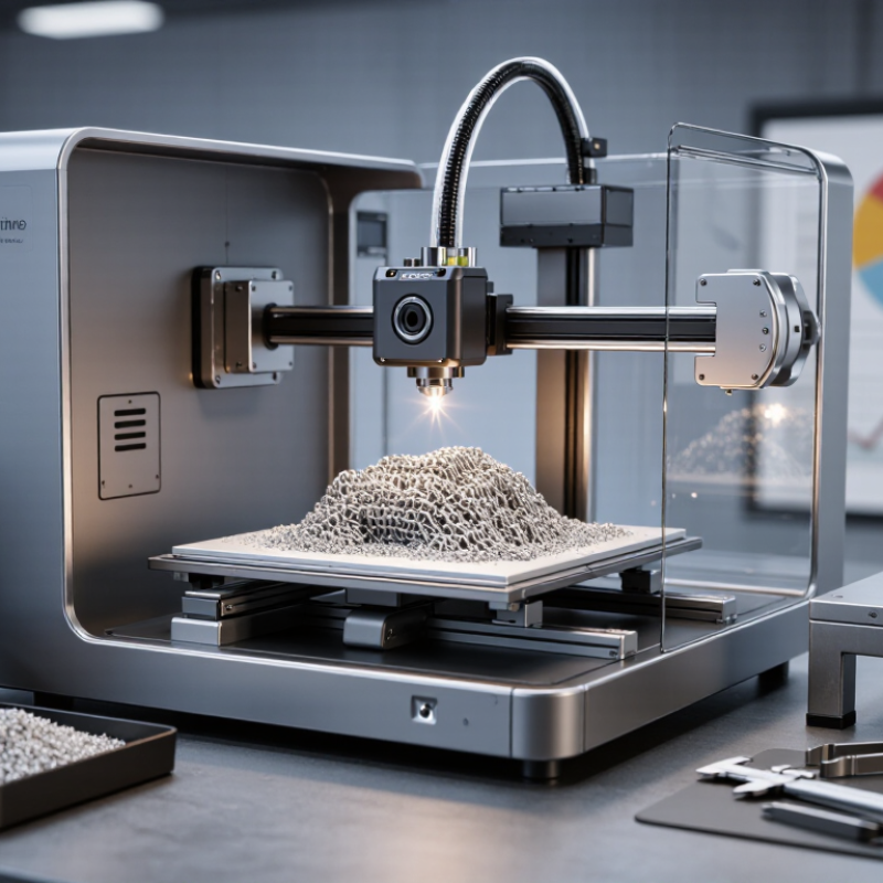
A metal 3D printer can build a component by selectively fusing fine powder, one cross-section at a time. In powder bed fusion, a thin layer of metal powder is spread across a build platform. A focused energy source melts chosen regions, following a digital design. The platform then moves down, and a fresh layer covers the fused one.
Each layer may be about 20–100 μm thick, or 0.02–0.1 millimeters. That is thin enough to form small features, but it does not guarantee a perfectly smooth surface. Very thin layers. They can capture finer vertical detail, yet usually require more passes and longer build times. Thicker layers may speed production, though small features and surface texture can change. The exact result also depends on the powder, machine settings, geometry, and later finishing.
The cycle repeats until the part is complete. Unmelted powder surrounds much of the component and can support some shapes during building. Overhangs may still need designed supports to steady the part and help manage heat. Many systems use a controlled atmosphere to limit unwanted reactions during melting. After the build, operators remove loose powder and supports, then may machine or polish critical surfaces. The word “print” sounds simple. In practice, heat distortion and tiny defects can make a seemingly minor design choice matter. Layer thickness is one setting, not a shortcut to quality.
How Directed Energy Deposition and Binder Jetting Build Metal Parts
What Is a 3D Printer for Metal?
A metal 3D printer makes parts by adding material in layers, but different systems use different methods. Directed Energy Deposition (DED) feeds metal wire or powder toward a focused heat source. The material melts as a nozzle follows a programmed path. DED can add features to an existing component or build a large part. Its deposited tracks may look uneven before finishing. That matters.
Binder jetting works differently. A roller spreads a thin layer of metal powder, then a printhead places liquid binder where each slice of the part should form. The result, often called a green part, is fragile and needs careful handling. It is later cured, cleaned of loose powder, and sintered in a furnace. During sintering, particles bond together and the part shrinks.
The practical choice depends on part size, geometry, production needs, and finishing plans. DED can suit repairs or parts with substantial material, though heat input may create distortion. Binder jetting can produce many smaller shapes without melting metal during printing, but shrinkage must be anticipated in the design. Neither method removes the need for inspection. A design that looks simple on screen may still warp, crack, or need machining. The process has trade-offs.
What Is a 3D Printer for Metal? - How Directed Energy Deposition and Binder Jetting Build Metal Parts
| Dimension | Directed Energy Deposition (DED) | Binder Jetting |
|---|---|---|
| How the process works | A focused heat source melts metal powder or wire as it is fed into the deposition zone. Material is added along a programmed toolpath. | A printhead selectively deposits a liquid binder onto successive layers of metal powder. The printed part is initially a fragile “green” component. |
| Typical feedstock | Metal powder or metal wire, depending on the equipment and application. | Fine metal powder, typically spread in thin layers across a build bed. |
| How layers bond | The heat source melts the feedstock and a small area of the existing part, creating a metallurgical bond as the material solidifies. | The binder holds powder particles together during printing. A later thermal process removes binder and fuses the particles. |
| Common heat sources or stages | Laser, electron beam, or electric arc systems are used to create the deposition heat. | Debinding removes much of the binder; sintering heats the part to bond powder particles. Infiltration may be used for some material systems. |
| Build approach | Often used to add features to an existing component, repair worn parts, or build larger near-net-shape structures. | Builds many components in a powder bed, with parts arranged throughout the available build volume. |
| Support and powder handling | Support requirements depend on part geometry and the deposition setup. Powder-based systems require powder handling; wire-fed systems do not use a powder bed. | Surrounding unbound powder supports many geometries during printing. Powder is removed after the build, and fragile green parts require careful handling. |
| Part density and shrinkage | Can produce dense, fully fused material when process parameters are controlled; local heat input can create residual stress or distortion. | Sintering causes shrinkage as the powder consolidates. Final density and dimensions depend on powder, binder, part geometry, and thermal processing. |
| Dimensional considerations | Bead size, heat input, deposition path, and machining allowance influence feature detail and final accuracy. Machining is often used for precision surfaces. | Part dimensions must account for sintering shrinkage. Fine features can be limited by powder size, binder spread, and the strength of the green part. |
| Typical post-processing | May include stress relief, machining, surface finishing, and inspection. | Typically includes depowdering, debinding, sintering, and often finishing or machining; the exact sequence depends on the material and part. |
| Common applications | Repair and cladding, adding material to existing parts, large metal structures, and components with localized features. | Batch production of relatively complex metal components, including parts suited to repeated production and efficient use of a build volume. |
| Key advantages | Can add material to existing components, accommodate large builds in suitable systems, and use wire or powder feedstock. | Can produce multiple parts in one build, does not require a laser or other melt source during printing, and can reduce the need for dedicated supports. |
| Key limitations | Heat management, residual stress, surface finish, and feature resolution can require careful process control and substantial finishing. | Parts need post-print thermal processing; sintering shrinkage, green-part fragility, and powder removal can constrain design and production. |
Note: Results vary with the metal alloy, machine configuration, process settings, part geometry, and post-processing. DED and binder jetting are distinct metal additive manufacturing methods; neither is universally best for every part.
Which Metal Alloys and Geometries Can Additive Manufacturing Produce?
Metal additive manufacturing builds parts layer by layer from powder or wire. Alloy choice depends on heat, corrosion, weight, wear, and performance requirements. Common options include stainless steel, aluminum alloys, titanium, nickel-based superalloys, cobalt-chromium, copper, and tool steels. Each behaves differently during melting and cooling. Titanium offers high strength at low mass, while nickel alloys tolerate sustained heat. Copper conducts heat well, but its reflectivity and thermal behavior can make processing demanding.
A metal printer can produce lattice cores, thin ribs, curved ducts, and enclosed cooling channels that are difficult to machine. Internal passages can reduce weight or guide fluid, but removing powder and inspecting hidden surfaces can be difficult. Not every shape works. Overhangs may need supports, which can leave marks or restrict access. Designers should consider wall thickness, powder escape openings, build direction, and finishing allowance. A narrow channel may close or distort.
The machine, process, alloy, and post-processing all set practical limits. Parts may need heat treatment, machining, or surface finishing to meet dimensional and fatigue requirements. Test coupons and inspection help confirm properties in the actual build, though results can vary with orientation. A clever shape can still be a poor part if it cannot be inspected or finished reliably.
How ASTM F3301-Guided Thermal Post-Processing Affects Finished Parts
A metal 3D printer builds parts layer by layer, but printing is only part of the process. Rapid heating and cooling can leave residual stresses inside the material. These stresses may cause a thin bracket to bend when support structures are removed. Thermal post-processing helps manage that risk.
ASTM F3301 provides requirements for thermal post-processing of metal parts made by additive manufacturing. It does not prescribe one universal furnace cycle. The appropriate treatment depends on the alloy, printing method, part geometry, and required properties. A controlled cycle may relieve stress or adjust the material’s strength and hardness. Temperature, hold time, cooling rate, and furnace conditions matter. Small differences can affect the finished part.
Process control continues after the furnace door opens. Keep traceable records of the cycle, and check representative parts or test coupons against the design requirements. Measurements can reveal distortion; mechanical tests can help confirm material performance. Yet a compliant cycle alone does not guarantee a good part. Build orientation, defects, and uneven wall thickness still matter. That is worth remembering. Manufacturers should validate the full process for the specific application, rather than assuming a standard treatment will suit every geometry.
Related Posts
-
What Are the Top Industrial Metal 3D Printers in 2026?
-
10 Key Factors to Choose the Best 3D Printer for Metal: Insights from 2023 Industry Trends
-
Navigating Export Certifications: How to Choose the Best 3D Printer for Metal in Global Markets
-
Top 5 Professional 3D Printers for High-Quality Prototyping and Design
-
Unlocking Business Potential with 3D Printers at the 2025 China Import and Export Fair
-
Exploring the Revolution of 3D Machine Printers for Custom Manufacturing Solutions