
10 ESS Connector Buying Tips for Global Buyers?
Buying an Ess Connector is not a small sourcing decision. It affects safety, installation time, thermal performance, and long-term maintenance. A connector may look simple on a warehouse shelf. Inside a battery cabinet, however, it carries heat, vibration, current, and responsibility.
The International Energy Agency reported that global battery-storage additions nearly doubled in 2023, reaching about 42 GW. BloombergNEF also expects stationary energy storage to expand rapidly through 2030. These figures signal stronger demand for dependable connection systems. They also expose a common mistake: choosing by price before checking current rating, mating cycles, ingress protection, and certification requirements. As energy-storage expert Dr. Imre Gyuk has stated, “Reliability is the foundation of energy storage.” That principle applies directly to every ESS Connector.
This guide presents ten practical buying tips for global purchasers. It examines conductor size, contact resistance, housing materials, locking design, temperature limits, and supplier traceability. It also considers regional standards and after-sales support. A connector rated for a clean laboratory may perform poorly beside a dusty outdoor inverter. Small details matter. A loose crimp can create heat. A weak seal can invite moisture. A rushed specification can become an expensive field problem.
The recommendations draw on IEA analysis, BloombergNEF market research, and established IEC practices. Still, no checklist replaces testing on the actual battery rack. That is where many assumptions fail. Buyers should request samples, verification reports, and clear change-control commitments before placing volume orders.
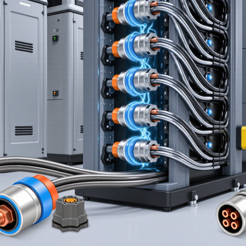
Define ESS Connector Needs: IEC 61984 Supports Up to 1,500 V DC
Global buyers should define the connector’s real electrical duty before comparing prices. IEC 61984 covers connector safety, testing, and performance requirements, including applications rated up to 1,500 V DC. This limit is not automatic approval for every connector. The final selection depends on rated current, insulation system, creepage distance, clearance, temperature, and installation conditions. A connector marked for 1,500 V DC may still fail under continuous high current or poor cooling.
The market is becoming less forgiving. The International Energy Agency reported that global battery demand exceeded 750 GWh in 2023, with electric vehicles representing about 90% of demand. IRENA also recorded 473 GW of new renewable capacity added worldwide in 2023. These figures indicate more battery racks, converters, and outdoor energy systems requiring dependable connections. Buyers should request IEC 61984 test evidence, temperature-rise data, mating-cycle results, and protection ratings. Do not rely on a voltage label alone.
Field experience suggests that small details create expensive faults. Check cable size, contact resistance, locking force, and service access before ordering. Confirm whether the connector handles repeated thermal cycling from daily charging and discharging. A spreadsheet can look complete and still miss vibration or condensation. That is an uncomfortable gap. It deserves a physical sample test, especially when systems operate near the 1,500 V DC boundary.
Match Current Ratings with Cable Size, Heat Rise, and Derating Curves
10 ESS Connector Buying Tips for Global Buyers
When selecting an ESS connector, match its current rating with the cable size, not just the label. A 40 A rating may assume a specific conductor, ambient temperature, and test method. Confirm that the terminal accepts the cable’s cross-section, insulation diameter, and crimp range. A loose crimp can create resistance, local heating, and early failure.
Check heat rise under the real operating current. Measure the connector near the contact interface, not only at the cable jacket. For example, a 25 A continuous load in a warm cabinet may produce more heat than a short 40 A peak. Review the manufacturer’s temperature-rise data and test samples with the planned cable, torque, and enclosure conditions. Small installation differences matter.
Derating curves deserve close attention. Bundled cables, restricted airflow, high ambient temperature, and repeated charge cycles can reduce the usable current. A connector rated at 60 A in free air may need a lower limit inside a crowded battery cabinet. I once focused too heavily on the headline rating and underestimated heat from adjacent terminals. That was a useful correction. Leave practical margin, document the assumptions, and ask for test evidence at your actual duty cycle. A simple thermal check can reveal more than a catalog table.
10 ESS Connector Buying Tips for Global Buyers? - Match Current Ratings with Cable Size, Heat Rise, and Derating Curves
Practical screening table for battery energy storage system power connections. Values are indicative engineering ranges for copper conductors and must be confirmed against the connector datasheet, installation method, local electrical code, and the complete thermal design.
| No. | Buying Tip | What to Check | Practical Screening Data | Why It Matters | Recommended Buyer Action |
|---|---|---|---|---|---|
| 1 | Match Continuous Current | Compare the ESS operating current with the connector's continuous current rating at the actual ambient temperature and installation condition. | Example: 120 A continuous load should not be paired with a connector rated only 100 A. A 150 A connector provides a 25% nameplate margin before other derating factors. | Connector ratings are commonly specified under defined test conditions. Enclosure temperature, cable bundling, duty cycle, and contact resistance can reduce the usable current. | Use the lowest applicable value from the connector rating, cable ampacity, fuse or breaker rating, busbar rating, and system thermal limit. |
| 2 | Match Cable Cross-Section | Confirm that the connector accepts the conductor cross-section, insulation diameter, crimp barrel, and cable construction. | Typical copper screening ranges: 25 mm²: about 77–101 A 35 mm²: about 96–125 A 50 mm²: about 125–150 A 70 mm²: about 160–195 A | Cable ampacity varies with insulation temperature, installation method, ambient temperature, grouping, and permissible voltage drop. A connector must not become the thermal bottleneck. | Check both the metric conductor size and the actual finished cable outside diameter. Do not select a terminal by cross-section alone. |
| 3 | Review Heat Rise | Evaluate the temperature rise at the rated current, including the contact pair, crimp area, cable entry, and nearby plastic parts. | Useful screening target: heat rise of approximately 30 K or less at the intended continuous current, unless the product standard or datasheet specifies another limit. | Excessive heat accelerates insulation aging, increases contact resistance, softens polymers, and can create thermal runaway at a poorly crimped or contaminated contact. | Request heat-rise curves or test data at the intended current rather than relying only on a marketing current number. |
| 4 | Apply Ambient Derating | Use the connector's current derating curve for the highest expected temperature inside the battery cabinet, PCS, or outdoor enclosure. | Illustrative calculation: a 200 A connector with a 0.80 derating factor at 70 °C has an effective screening current of 160 A. | Many ratings are established around 20–25 °C ambient. An enclosure exposed to solar heating or adjacent busbars may operate well above that reference. | Design for the maximum measured or calculated local temperature, not the general room temperature. |
| 5 | Account for Grouping | Check whether several energized cables or connectors are installed side by side, in a loom, or within a confined cable channel. | Screening example: apply a 0.70–0.85 grouping factor when multiple loaded circuits share a restricted thermal path, then verify the manufacturer's curve. | Adjacent current-carrying conductors raise the local air and surface temperature, reducing the heat-transfer capability of each cable and connector. | Ask for derating data for the actual number of poles, energized circuits, cable orientation, spacing, and enclosure arrangement. |
| 6 | Check Contact Resistance | Review initial and end-of-life contact resistance, crimp resistance, and the test current used by the supplier. | Engineering screening value: a high-current contact pair is often targeted at a few milliohms or less; every 1 mΩ at 150 A produces about 22.5 W of local heat. | Power loss follows P = I²R. A small resistance increase has a large effect at ESS current levels and can concentrate heat at one contact. | Request resistance limits, measurement method, aging results, and resistance after mating-cycle, vibration, humidity, and thermal-cycle tests. |
| 7 | Verify Duty Cycle | Distinguish continuous current from short-duration charge, discharge, inrush, pre-charge, fault, and peak-current conditions. | Example: a connector may carry 180 A continuously but require a separate short-time or pulse rating for a 250 A event. Pulse capability must not be assumed from the continuous rating. | Thermal mass may tolerate a short pulse, while the same current held continuously can exceed the connector's temperature limit. | Provide the supplier with an actual current-time profile, including RMS current where applicable, rather than one maximum-current value. |
| 8 | Control Voltage Drop | Calculate voltage drop across both connector interfaces, crimp joints, cable length, and any fuse or busbar connection. | Example: at 150 A, a total resistance of 2 mΩ causes a 0.30 V drop and 45 W of loss across the complete path. | Voltage drop reduces converter efficiency and increases heat. In low-voltage battery systems, even a few hundred millivolts can be significant. | Set a project voltage-drop limit, such as 0.5–1.0% of nominal DC voltage for a critical high-current connection, and verify it by test. |
| 9 | Validate Crimp and Assembly | Confirm conductor-strand compatibility, crimp-tool calibration, pull-out force, crimp height, inspection criteria, and sealing method. | Typical practice: use the specified die and tooling for the exact terminal; do not substitute a general-purpose lug or hand crimper for a controlled high-current crimp. | A loose, over-compressed, under-compressed, or contaminated crimp can create localized resistance that is not visible during a basic continuity check. | Require crimp validation samples, pull-test records, resistance checks, and traceable assembly instructions for production and field replacement. |
| 10 | Check Safety and Service Life | Review touch protection, keyed mating, locking, HVIL or interlock needs, IP protection, creepage, clearance, flammability, vibration, and mating-cycle endurance. | Common application targets: IP67 when properly mated for temporary immersion protection; 1,000 or more mating cycles only when explicitly specified; voltage and pollution limits must be confirmed for the installation. | ESS connectors may face high DC voltage, stored energy, condensation, vibration, dust, and repeated maintenance operations. Current capacity alone does not establish system safety. | Request complete qualification evidence for the intended DC voltage, altitude, humidity, temperature range, short-circuit environment, and service procedure. |
Important design note: The cable ampacity examples are broad screening ranges for copper conductors under commonly used low-voltage installation assumptions. Final selection must use the applicable IEC, NFPA, UL, or national code method, conductor insulation temperature, installation method, ambient temperature, grouping factor, voltage drop, fault current, and the connector manufacturer's published derating curves.
Verify Safety Through UL 1973, UL 9540, and IEC 60529 IP Ratings
10 ESS Connector Buying Tips for Global Buyers
Verify Safety Through UL 1973, UL 9540, and IEC 60529 IP Ratings
Safety verification should begin with the complete energy storage system, not the connector catalogue. UL 1973 evaluates battery systems and their components for stationary applications. UL 9540 addresses the broader energy storage system, including electrical, control, and protective functions. A connector may support compliance, but it does not automatically prove system certification.
Ask suppliers for current certificates, test reports, and the exact model numbers covered. Check voltage, current, temperature, mating cycles, and installation conditions. A certificate with a similar-looking connector is not enough. In procurement reviews, small suffixes can change the approved configuration. Labels can mislead.
IEC 60529 IP ratings show protection against dust and water. IP65 differs from IP67, especially when equipment faces temporary immersion. Confirm whether the rating applies to mated connectors, cable assemblies, or empty housings. Inspect seals, locking mechanisms, and strain reliefs before shipment. Request photographs from production samples, not only drawings. A useful detail is often overlooked: condensation inside an enclosure can still damage contacts. No rating solves poor installation.
Global buyers should also compare documentation quality. Reliable records include revision dates, laboratory references, operating limits, and traceable test samples. I would not accept “IP rated” without the two digits. I would also question certificates that omit environmental conditions. Standards help, but judgment remains necessary. Even experienced teams can miss one detail.
Check Global Compliance with RoHS, REACH, and IEC 60664 Requirements
Global buyers should treat ESS connector compliance as a design requirement, not a document exercise. RoHS limits ten restricted substances, including lead, mercury, and certain flame retardants. REACH also requires communication when a Candidate List substance exceeds 0.1% by weight in an article. ECHA’s 2024 enforcement project reported non-compliance in 18% of 2,407 products inspected. That figure deserves attention.
Check plating, housing resin, seals, and solder interfaces. A general RoHS statement may not cover process changes or subcomponents. Ask for test methods, report dates, and laboratory accreditation. REACH evidence should identify applicable SVHCs and the supply-chain response process. Keep revision-controlled records. A spreadsheet is not proof.
IEC 60664 adds electrical safety concerns. Verify clearance, creepage distance, insulation system, pollution degree, overvoltage category, and altitude assumptions. The connector may pass a material review but fail under condensation, dust, or high switching voltage. IEC 60664-1 provides the insulation-coordination framework; actual spacing still depends on the equipment design. A connector rated for one environment may be unsuitable elsewhere.
I have seen buyers copy catalogue ratings without checking pollution conditions. That shortcut is risky, and easy to overlook.
Compare Suppliers by IEC 60512 Testing, Traceability, Lead Time, and Cost
For global ESS buyers, connector selection should begin with evidence, not a low unit price. IEC 60512 testing can reveal contact resistance, insulation performance, mechanical endurance, and environmental behavior. Ask for test methods, sample conditions, acceptance limits, and recent reports. A certificate alone is not enough. The report should match the exact connector design, plating, cable size, and locking system. Small differences matter in high-current storage cabinets. Keep photos and serial records. They help when a shipment looks different.
Tips: Compare suppliers in one table. Record IEC 60512 results, traceability depth, quoted lead time, minimum order, tooling fees, and landed cost. Traceability should connect raw material, production lot, inspection data, and shipment carton. Lead time needs detail. Separate sample approval, tooling, production, and transport. A “fast” quote may exclude validation or freight. Ask for capacity evidence during peak demand. Do not assume.
Cost should include field risk, not only purchase price. A cheaper connector may require extra inspection, rework, or replacement inventory. Request a cost breakdown and clarify warranty, packaging, storage limits, and change-notification procedures. For critical interfaces, test samples under realistic vibration, temperature, mating cycles, and current loads. IEC 60512 supports disciplined comparison, but it cannot replace application-specific validation. I would also challenge my own checklist: paperwork can look complete while production remains inconsistent. A remote audit may expose that gap. Give corrective actions a clear deadline.
10 ESS Connector Buying Tips for Global Buyers
Recommended RFQ weighting for evaluating ESS connector suppliers by IEC 60512 test evidence, traceability, electrical safety, delivery performance, and total cost.
The percentages are a transparent procurement-planning model, not company or brand data. Buyers should verify the applicable IEC 60512 test reports, material records, batch traceability, environmental ratings, production capacity, and landed cost for each program.